





Check whether a pair of spur or helical gears will survive, and see why.
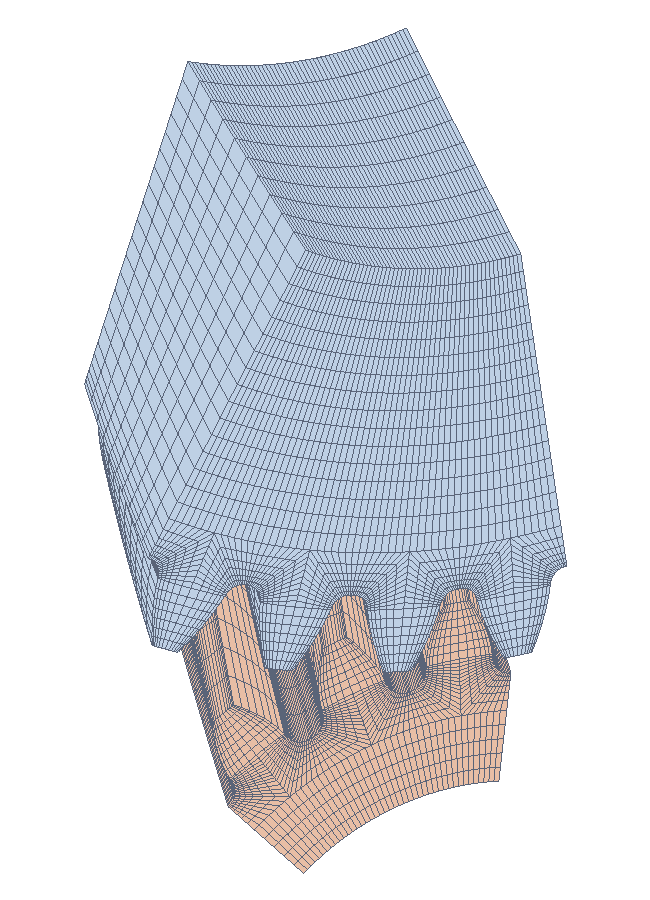
python-gearbox calculates the two classic failure modes of gear teeth — surface pitting and tooth root breakage — with ISO 6336:2019 and AGMA 2001-D04, the standards gear designers use. When you want to look closer than a standard can, it builds finite-element meshes of the real tooth shape and solves them with the free CalculiX solver: you can watch the stresses move as the teeth roll through mesh.
What you can do with it:
- Rate a gear pair for pitting and bending with ISO 6336 (parts 1, 2 and 3) or AGMA 2001-D04, with every intermediate factor available for inspection.
- Handle the less common cases: helical, double helical and internal gears, shaper-cut teeth, static and limited-life loads.
- Choose profile shifts that balance the pair or lower the contact stress.
- Export one tooth to MATLAB/COMSOL, ABAQUS or ANSYS.
- Mesh and solve with finite elements a single gear or a pair in mesh, in 2D or 3D.
Lengths are in mm, angles in degrees, stresses in MPa, power in kW and speeds in rpm.
Documentation — start with the illustrated engineering guide, or go directly to the section you need:
- Gear geometry: generated teeth, involutes, meshing and the contact path.
- Strength theory: contact and bending foundations, ISO 6336, AGMA and a reproducible comparison.
- Finite elements: 2D and 3D models, contact and root-stress results, assumptions and validation limits.
- Optimization and API reference.
The Docs workflow builds and publishes this site after every push to master; pull requests
build the guide without publishing. In repository Settings → Pages, the source is
GitHub Actions, not a gh-pages branch. The workflow can also be run manually from master
with publish=true. Failed documentation builds do not reach the deployment job.
pip install "python-gearbox @ git+https://github.com/efirvida/python-gearbox"       # strength calculations
pip install "python-gearbox[fem] @ git+https://github.com/efirvida/python-gearbox"  # plus meshing and plots
Version 0.2 is not on PyPI yet: pip install python-gearbox still installs the 0.1 release of 2015,
with a different API. Once 0.2 is published, pip install python-gearbox and
pip install "python-gearbox[fem]" will do.
The finite-element analyses also need CalculiX, a separate program: install it with
conda install -c conda-forge calculix or apt install calculix-ccx, and make sure ccx is on
your PATH (or point the GEARBOX_CCX environment variable at it).
Describe the cutting tool, the material, both gears and how the pair is driven, then ask for the pitting check:
from gearbox import Gear, Lubricant, Material, MaterialType, ShaftArrangement, Tool, Transmission
from gearbox.standards import iso6336

tool = Tool(addendum_coefficient=1.0, dedendum_coefficient=1.25, root_fillet_radius_coefficient=0.38)
steel = Material(
    material_type=MaterialType.NITROCARBURIZED_STEEL,
    contact_stress_limit=1500.0, bending_stress_limit=460.0, brinell_hardness=286.7,
)
pinion = Gear(
    tool=tool, material=steel, number_of_teeth=22, module=2.5, face_width=34.0,
    quality_grade=6, surface_roughness=3.67, shaft_diameter=35.0,
    shaft_arrangement=ShaftArrangement.BETWEEN_BEARINGS_TOWARDS_TORQUED_END,
    bearing_span=60.0, offset=15.0, favorable_contact=True,
)
wheel = Gear(
    tool=tool, material=steel, number_of_teeth=40, module=2.5, face_width=34.0,
    quality_grade=6, surface_roughness=3.67, shaft_diameter=50.0,
    shaft_arrangement=ShaftArrangement.BETWEEN_BEARINGS_TOWARDS_TORQUED_END,
    bearing_span=60.0, offset=35.0, favorable_contact=True,
)
transmission = Transmission(
    pinion=pinion, wheel=wheel, lubricant=Lubricant(kinematic_viscosity_40c=160),
    pinion_speed_rpm=1450.0, power_kw=40.0, design_life_hours=10_000.0, application_factor=1.3,
)

result = iso6336.calculate_pitting(transmission)
print(result.contact_stress_pinion, result.safety_factor_pinion)
result carries the contact stress of each gear, the stress it may take and the resulting safety
factor, plus every factor of the standard (dynamic_factor, life_factor_pinion, …) under its
full name; the standard's symbol is in each field's docstring. iso6336.calculate_bending does the
same for the tooth root, and gearbox.standards.agma2101 offers both checks with AGMA.
A few things worth knowing:
- Every model is immutable. To try a variant, copy it with
dataclasses.replace, for instancereplace(transmission, power_kw=50). - Choices that pick a table of the standard are named, not numbered:
MaterialType,ShaftArrangement(ISO 6336-1 figure 13),LeadModification,FlankModification,Crowning,AssemblyCondition,GearingType. Helical pairs assume unmodified flanks (FlankModification.NONE, the safe side) unless you say otherwise. - Double helical gears: set
double_helical=Trueon both gears and giveface_widthas the width of one helix (ISO 6336 only). - Internal gears: set
internal=Trueon the wheel, keepnumber_of_teethpositive, use a shaper cutter (Tool(cutter_type="shaper", cutter_teeth=…)) for the bending check, and chooseTransmission(dynamic_factor_method="C").
Coming from version 0.1? Version 0.2 follows the 2019 edition of ISO 6336 instead of the 2006 one and fixes a number of errors of the original code, so your numbers will change. Each change and its effect is listed in KNOWN_ISSUES.md; the new names of the API are in Upgrading from 0.1.x.
The standards reduce a tooth to a handful of factors. The gearbox.fem module lets you look at the
tooth itself: it meshes the exact shape the hob cuts, root fillet included, and solves it with
CalculiX.
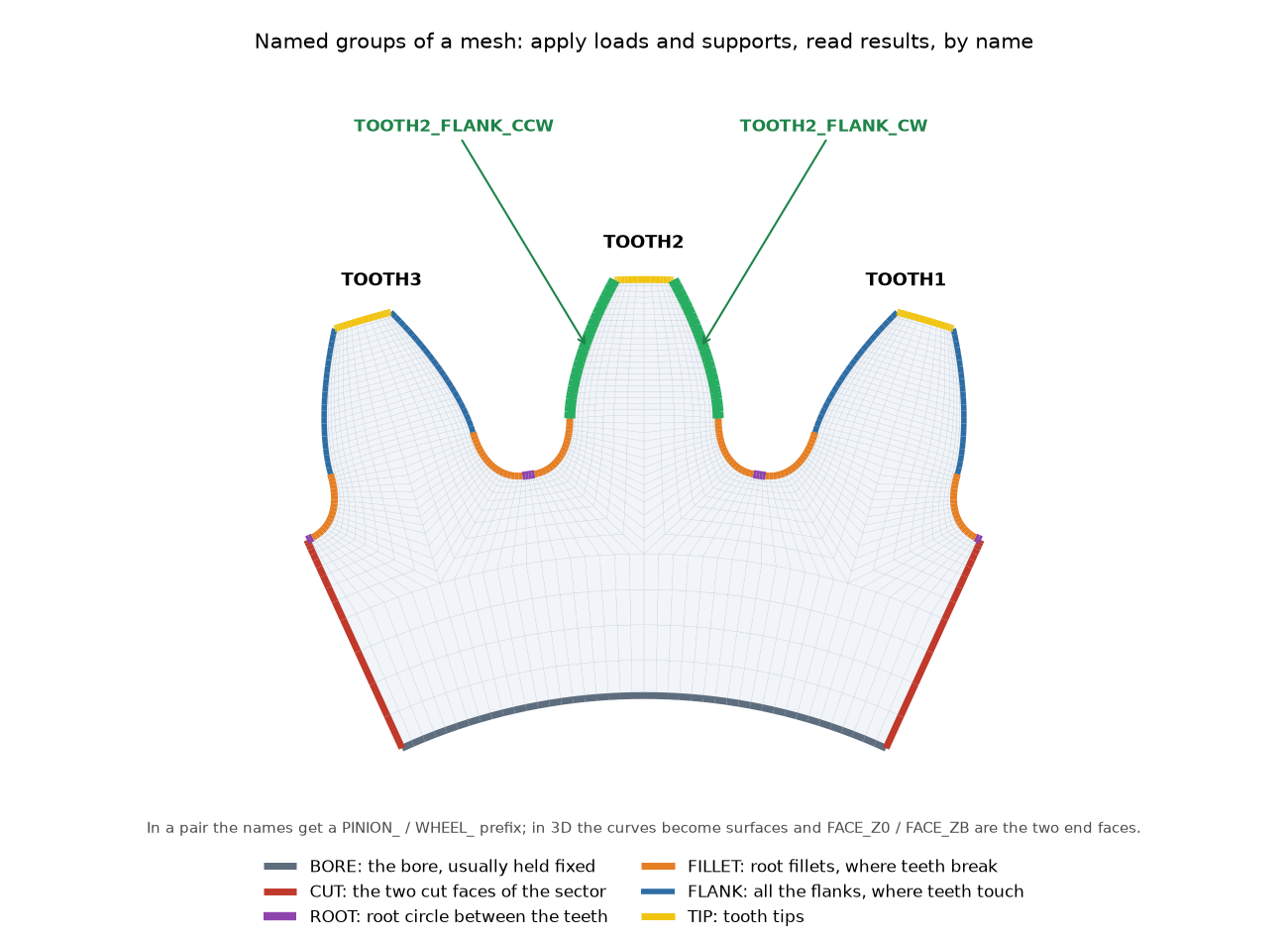
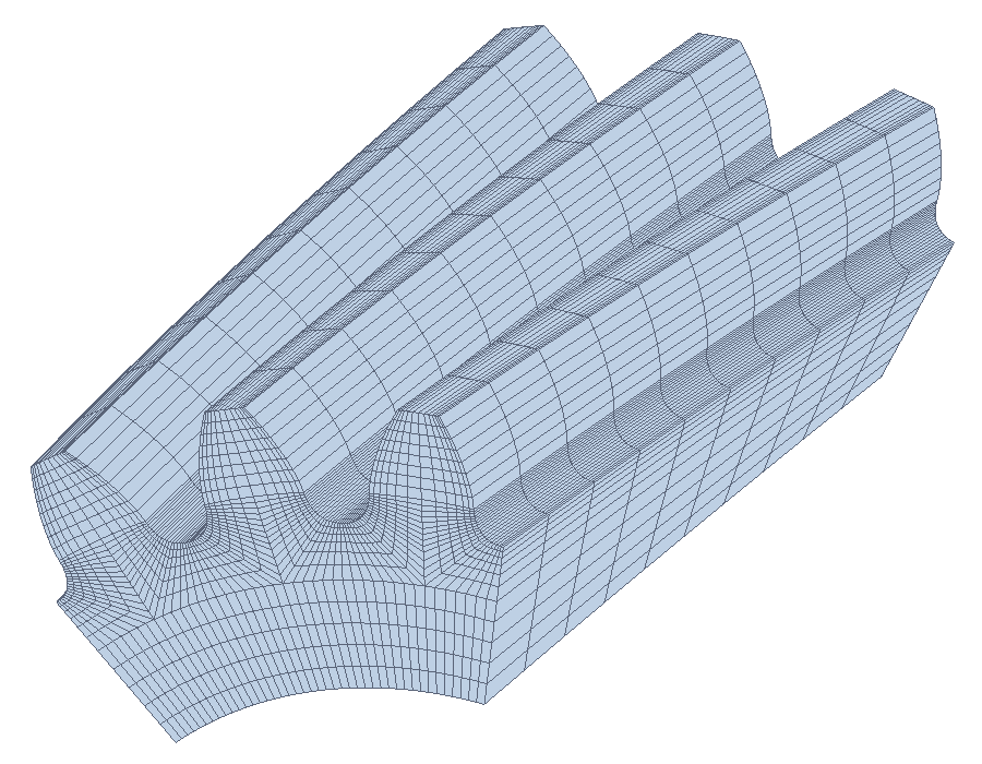
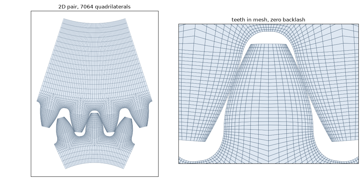
mesh_gear meshes a few teeth of one gear and mesh_pair a pinion and wheel in mesh, in 2D
(quadrilaterals) or 3D (hexahedra, twisted along the helix). The meshes are structured, finest at
the flank and in the root fillet where the stresses peak, and come with named groups (FLANK,
FILLET, BORE, TOOTH2_FLANK_CCW, …) so you can apply loads and read results without picking
nodes by hand. They are written as Gmsh .msh or Abaqus/CalculiX .inp files.
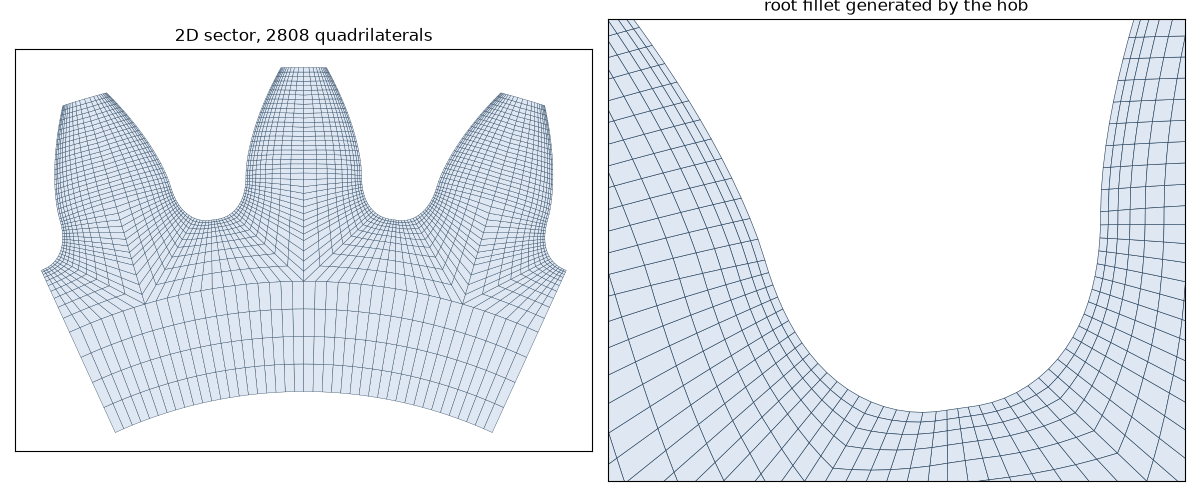
Each tooth is split into a few four-sided blocks. By default ("fillet_block") the root fillet gets
a block of its own, which keeps the elements regular even when the tooth is undercut and lets you
refine the critical root section on its own. The simpler "standard" layout is still available:
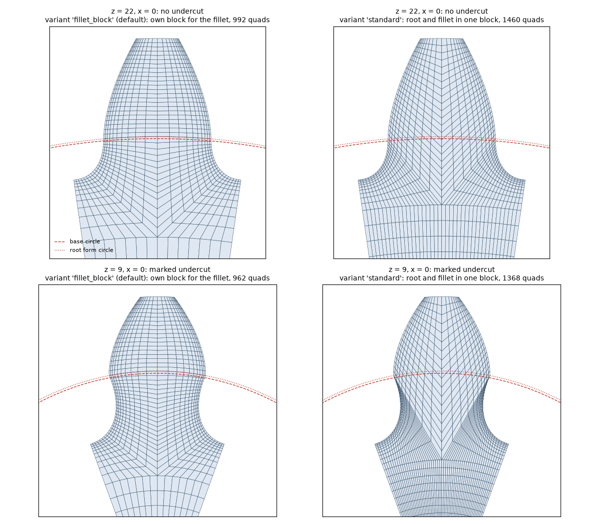
The snippets in this section continue A first calculation: pinion and
transmission are the ones defined there.
from gearbox.fem import mesh_gear, solve_bending, solve_contact

mesh_gear(pinion, "out", "pinion", "3D", teeth=3, formats=("msh", "inp"))
bending = solve_bending(transmission, "out", dimension="2D")  # force and load point from the pair
contact = solve_contact(transmission, "out")                  # teeth touching at the pitch point
print(bending.max_principal_stress, contact.max_contact_pressure)solve_bendingpushes on one tooth flank and holds the bore. Given the transmission, it takes the nominal tangential force from it and loads the tooth where ISO 6336-3 does, at the outer point of single pair contact (member="wheel"checks the wheel); the 2D root stress lands within 2-12 % of the standard. A singleGearworks too, with the force given by you.solve_contactturns the pinion against the wheel until it carries the design torque, with frictionless contact between all the flanks of the model. At the pitch point the contact pressure matches Hertz' theory within 1 %.
Because the pair can be meshed at any angle, you can follow a tooth all the way through mesh. That is what these two animations show for a spur pair (22 and 40 teeth, module 2.5, 8000 N):
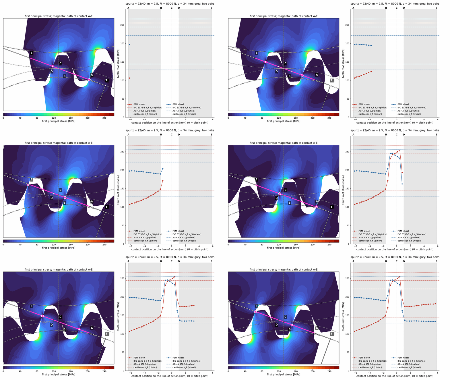
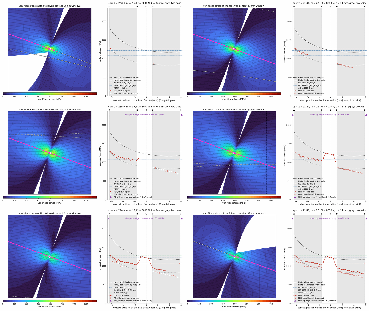
On the left, the stresses are drawn under the classic scheme of the mesh: the base and pitch circles
and the line of action, with the path of contact A-E in magenta. On the right, the result for the
followed tooth as it moves from A to E:
- In the grey zones two pairs of teeth share the load. The contact pressure sits between Hertz for the whole load and for half of it, and the root stresses stay low.
- Between
BandDone pair carries everything. The contact pressure follows Hertz for the whole load and the root stresses reach their peak, close to what ISO 6336-3 predicts. - Just outside
AandEthe sharp tip of a tooth still touches, because loaded teeth bend. This is why real gears get tip relief. The pressure at a sharp edge has no finite value, so it is marked but kept off the scale.
The horizontal lines are the plain values of each method (all load factors set to 1): ISO 6336-3,
AGMA 908 and a simple cantilever beam for bending; Hertz, ISO 6336-2 and AGMA 2001 for contact.
Each method idealises the load differently, so they are a reference rather than something the
curves should hit. The figures are built by
docs/figures/make_figures.py.
The tools behind these figures live in gearbox.fem.post: LineOfAction (the points A to E,
the single and double contact zones, Hertz' pressure along the line), contact_sweep (solve the
contact at several positions along the path, with a cache), contact_patches (the contact of each
tooth) and plot_mesh, plot_field and plot_line_of_action for matplotlib.
import matplotlib.pyplot as plt
from gearbox.fem.post import LineOfAction, contact_sweep, plot_field, plot_line_of_action

line = LineOfAction.of(transmission)  # the pair of "A first calculation"
# solve near the start of contact (two pairs share the load) and at the pitch point;
# a few minutes per position, cached in the folder "sweep"
points = contact_sweep(transmission, "sweep", [line.points()["A"] + 1.0, 0.0])
fig, ax = plt.subplots(figsize=(8, 7))
plot_field(ax, points[1].stress("von_mises"))
x, y = line.point(0.0)  # zoom on the pitch point, then draw the scheme over it
ax.set_xlim(x - 8, x + 8)
ax.set_ylim(y - 7, y + 7)
plot_line_of_action(ax, line, points[1].followed.point)
fig.savefig("contact.png")
examples/08_fem_post_processing.py walks through it step
by step.
Each example is a short guided tour: it explains what it does step by step and prints a result you can read. Start with the first one and go on in order:
| Example | What you learn |
|---|---|
01_basic_calculation.py |
Describe a gear pair, check it with ISO 6336 and AGMA 2001, read the verdict |
02_helical_gears_and_what_if.py |
Fix a failing design: wider face, helix angle, harder steel; the largest power it carries |
03_profile_shift_optimization.py |
Share the profile shift between pinion and wheel to balance the pair |
04_export_geometry.py |
Take the tooth geometry to COMSOL, ABAQUS or ANSYS |
05_fem_mesh.py |
Mesh a gear and a pair in 2D and 3D, named groups and element quality |
06_fem_bending.py |
Root stress of a tooth with CalculiX, side by side with ISO 6336-3 |
07_fem_contact.py |
Contact stress of two teeth with CalculiX, checked against Hertz |
08_fem_post_processing.py |
Follow a tooth through mesh and see how two pairs share the load |
The calculation follows the formulae of each standard closely; the tests cite the clause they check. For each standard, what is in and what is not:
| Standard | Implemented | Not implemented |
|---|---|---|
| ISO 1328-1:2013 | flank tolerances f_pT, F_pT, F_αT, F_βT, f_fαT, f_HαT, f_HβT, f_fβT (formulae 5-12) |
runout, tooth thickness |
| ISO 6336-1:2019 | K_A, K_γ (given), K_v by method B, method C or a measured value (A), K_Hβ/K_Fβ (method C), K_Hα/K_Fα (method B), tooth stiffness c', c_γα, c_γβ (method B) |
method A/B of K_Hβ, K_v method B for internal gears, multi-mesh resonance (idlers, planets) |
| ISO 6336-2:2019 | pitting, method B, reference, limited-life and static stress (Z_H, Z_E, Z_ε, Z_β, Z_B, Z_D, Z_NT with and without limited pitting, Z_L, Z_v, Z_R, Z_W, Z_X); internal and double helical gears |
the standard gives no formula for Z_B/Z_D when ε_α > 2 (clause 6.4), which raises no error but is outside the validated range |
| ISO 6336-3:2019 | tooth breakage, method B, external gears cut with a hob or a shaper cutter and internal gears cut with a shaper cutter; double helical gears; reference, limited-life and static stress; Y_Sg for grinding notches |
the graphical Y_δrelT for static stress of St without a yield point |
| AGMA 2001-D04 / 908-B89 | pitting and bending stress, I and J (checked against the 908-B89 tables), K_v, K_s, K_m, K_B, K_o; allowable stresses and safety factors with Z_N, Y_N, C_H, K_T, K_R when s_ac/s_at are given; pitting of internal gears |
bending of internal gears (908-B89 gives no J), double helical gears, cast-iron stress cycle factors, the critical-service curves of Z_N, s_ac/s_at tables (the numbers must be supplied) |
Some pieces are missing, usually because the source they need was not available to check them
against. Where a missing piece would make a result wrong, the call raises a ValueError instead of
returning a doubtful number (marked raises below). Details are in
KNOWN_ISSUES.md.
- Internal gears (raises): AGMA bending (AGMA 908 gives no
Jfor them), the dynamic factor by method B, profile shift optimisation and geometry export. Interference checks between pinion and ring are not done (they need ISO 21771). - Double helical gears with AGMA (raises): the clauses of AGMA 2001-D04 on face width and
K_mfor this type were not available to check. - Contact ratio: limited by the base circle (ISO 6336-2 formula 33) but not yet by the active root diameter (formulae 34-35, they need ISO 21771).
- ISO 6336: methods A and B of
K_Hβ; dynamics of idlers and planetary stages; the graphicalY_δrelTfor static bending of steels without a yield point.Z_BandZ_Dabove a contact ratio of 2 are computed but fall outside what the standard covers (it gives no formula there). - AGMA 2001-D04: stress cycle factors of cast iron (raises) and the critical-service edge of
Z_N. The allowable stress numberss_acands_atare inputs, not tables. - ISO 1328-1: runout and tooth thickness tolerances.
- Finite elements: external gears only (raises for internal ones), cut with a hob (no protuberance or shaper cutter). The
analyses are linear elastic and frictionless and were validated in 2D.
solve_contactruns in 3D too, but a mesh coarse enough to finish in half an hour overestimates the contact pressure by about 15 %, and a fine one is very slow.
The API was redesigned with descriptive names. The main changes:
| 0.1.x | 0.2 |
|---|---|
Gear(z=…, m=…, x=…, b=…, bs=…, sr=…, rz=…, precision_grade=…, schema=…, l=…, s=…, gear_crown=…, helix_modification=…, gear_condition=…) |
Gear(number_of_teeth, module, profile_shift_coefficient, face_width, web_thickness, rim_thickness, surface_roughness, quality_grade, shaft_arrangement, bearing_span, offset, crowning, lead_modification, assembly_condition) |
Transmission(gears=[g1, g2], rpm_in, p, l, ka, sh_min, sf_min, gear_box_type) |
Transmission(pinion, wheel, pinion_speed_rpm, power_kw, design_life_hours, application_factor, min_safety_factor_pitting, min_safety_factor_bending, gearing_type) |
iso.Pitting(t).calculate()['sigmaH'] |
iso6336.calculate_pitting(t).contact_stress_pinion |
agma.Bending(t).calculate()['sigmafone'] |
agma2101.calculate_bending(t).bending_stress_pinion |
Optmization(t).bending() |
optimization.maximum_profile_shifts(t) / minimum_contact_stress_profile_shifts(t) |
ExportGear(g).matlab_comsol(…) |
export.export_gear(g, ExportTarget.COMSOL, …) |
helix_modification=1…5 |
LeadModification; numbering of ISO 6336-1:2019 table 12: old 1 and 2 are unchanged, old 3, 4, 5 are now HELIX_CORRECTION (4), HELIX_CORRECTION_AND_CENTRAL_CROWNING (5), END_RELIEF (6) |
schema=1…5 |
ShaftArrangement (same numbers, now named after figure 13 a to e) |
pip install -e ".[dev]"
pytest
ruff check . && ruff format --check src tests
Two kinds of tests protect the numbers:
- Formula tests check each factor against the standard, with the clause in a comment.
- Golden tests (
tests/golden/) pin the complete results of six reference designs.reference.jsonis the current reference (python tests/golden/regenerate_reference.pyregenerates it);baseline_original.jsonkeeps the numbers of the original 0.1 code. A change that moves them has to be intentional and explained in the commit and in KNOWN_ISSUES.md.
The standards themselves are not part of the repository. The calculation was reviewed against ISO 6336-1/-2/-3:2019, ISO 6336-5:2016 and AGMA 2001-D04.
Contributions are welcome: see CONTRIBUTING.md, the Code of Conduct and the security policy. What changed between versions is in CHANGELOG.md.
MIT — see LICENSE.
If you use python-gearbox in your research, please cite it. The DOI 10.5281/zenodo.3660526 stands for all versions and resolves to the latest one; each version also has its own DOI on Zenodo (0.2.0: 10.5281/zenodo.23594908). GitHub's "Cite this repository" button gives the same reference from CITATION.cff.
BibTeX:
@software{firvida_python_gearbox,
  author    = {Fírvida Donéstevez, Eduardo Miguel},
  title     = {python-gearbox: gear strength with ISO 6336 and AGMA 2001,
               and finite-element analysis of gear teeth},
  publisher = {Zenodo},
  version   = {0.2.0},
  year      = {2026},
  doi       = {10.5281/zenodo.3660526},
  url       = {https://doi.org/10.5281/zenodo.3660526}
}
APA:
Fírvida Donéstevez, E. M. (2026). python-gearbox: gear strength with ISO 6336 and AGMA 2001, and
finite-element analysis of gear teeth (Version 0.2.0) [Computer software]. Zenodo.
https://doi.org/10.5281/zenodo.3660526